Compression Limiters
Metal Compression Limiters provide and maintain bolted joint integrity of a plastic assembly. Compression Limiters are designed to protect the plastic components of an assembly from the compressive loads generated when a bolt is tightened to its recommended tightening torque, thereby assuring that the joint remains intact throughout the life of the product.
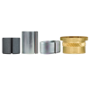
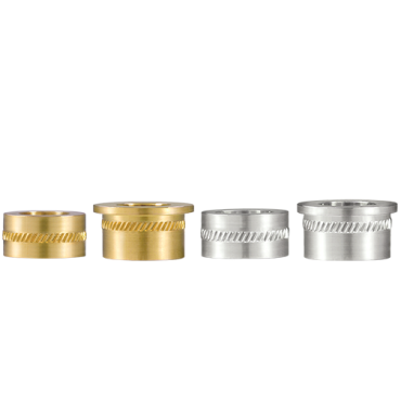
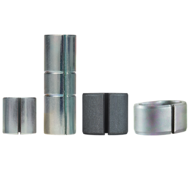
SPIROL offers a range of both formed and machined Compression Limiters including split seam, molded in, oval and solid wall designs. Each type of Compression Limiter is designed to accommodate different compressive loads, positional tolerances and installation methods. All formed Compression Limiters, except the Series CL220, are zinc plated and have a supplementary coating of trivalent passivation and an organic sealant for corrosion resistance. This finish provides 144 hours to white corrosion, and 384 hours to red corrosion when salt spray tested in accordance with ASTM B117. SPIROL’s Series CL220 Compression Limiters are coated with ArmorGalv®, a zinc alloy thermal diffusion coating that provides a minimum of 1000 hours corrosion resistance to red rust. Machined Limiters are manufactured from aluminum and brass, both of which have inherent corrosion resistant properties and thus do not require supplementary finishing.
The clearance between the bolt and the inside diameter of the installed Compression Limiter is adequate to meet normal misalignment. The Compression Limiter’s length should be designed to ensure it will bottom out against the surface under the bolt’s head and mating component. The appropriate length and length tolerance is application dependent. While the standard tolerance is sufficient to meet most needs, verification is recommended. SPIROL‘s Applications Engineers are available to assist in this process. If it is determined that a special Compression Limiter is required, then a documented recommendation will be provided.
It is imperative that the proper Compression Limiter be designed into each application based on the specific requirements for that assembly, and that the plastic host be designed appropriately to ensure that bolted joint integrity is maintained throughout the life of the assembly. SPIROL’s Application Engineers are available to work with you to determine the most appropriate Compression Limiter for your application.

Compression Limiter Types
SPIROL offers a comprehensive line of split seam, molded in, oval and solid wall designs to accommodate different compressive loads, positional tolerances and installation methods for bolts ranging in size from M3 to M12 and #4 to 3/8” - depending on the type of Compression Limiter. For simplicity, SPIROL has broken down the different types by the two different installation methods below: Post Mold Installed Compression Limiters and Molded-In Compression Limiters. Some series of Compression Limiters can be either pressed in or molded in, while others can only be installed by one method.
If one of SPIROL's standard Compression Limiters does not meet your needs, our Application Engineers will work with you to design a custom Compression Limiter to meet your unique requirements. Select from the options below for more specificity about SPIROL's Compression Limiter offering or contact us for complimentary technical support!
Standard Offering Breakdown & Materials
| SERIES | DIA. RANGE |
INSTALLATION METHOD |
MATERIAL | BOLT RATING | RETENTION FEATURE / ATTRIBUTES | ||
| TYPE | GRADE | CLASS | GRADE | ||||
| CL220 | M4 - M12 | Press-In | B - High Carbon Steel | UNS G10700 / G10740 CS67S (1.1231) / CS75S (1.1248) |
8.8 | 5 | Radial Tension / ArmorGalv® |
| CL200 | M4 - M8 | Press-In | 8.8 | 5 | Radial Tension / Reduced Profile | ||
| CL350 | M6 - M8 | Press-In | 10.9 | 8 | Radial Tension / Heavy Wall | ||
| CL400 | M6 - M8 | Press-In | 8.8 | 5 | Radial Tension / Oval | ||
| CL460 | M6 - M8 | Mold-In | 8.8 | 5 | Radial Groove / Oval | ||
| CL500 | M6 - M8 / #10 - 5/16 |
Mold-In | F- Low Carbon Steel | UNS G10060 / G10100 EN10139 DC04 (1.0338) / DC01 (1.0330) |
8.8 | 5 | Radial Groove / Round |
| CL6000 | M3 - M10 | Either Press-In or Mold-In |
A - Aluminum | ASTM B211 2024 ISO AlCu4Mg1 |
10.9 |
8 |
Knurled / Solid Wall / Lightweight / Lead Free |
| CL6100 | CL6000 w/ Head | ||||||
| CL8000 | E - Brass | UNS C36000 EN 12164 CW603N CuZn36Pb3 |
Knurled / Solid Wall / Cathodic Alt. to Aluminum | ||||
| CL8100 | CL8000 w/ Head | ||||||
| CL620 | M3 - M8 | A - Aluminum | ASTM B211 2024 ISO AlCu4Mg1 |
Knurled / Solid Wall / Lightweight / Lead Free | |||
Don’t See What You’re Looking For?
Need help choosing the most appropriate fastening solution for your application? SPIROL's Application Engineers will review your specific requirements, and design the most cost-effective Compression Limiter to meet your technical and commercial needs. Let us help!

Recommended Tightening Torque
The integrity of the bolted joint requires that none of the components, including the bolt, be stressed beyond the elastic limit. SPIROL recommends a clamping load not to exceed 75% of the proof load of the bolt. The recommended torque values to produce this clamping load are provided below.
Determination of Compression Limiter Length
Proper length specifications of both the Compression Limiter and the plastic component are crucial to the proper performance of the bolted joint. The recommended maximum length of the Compression Limiter is the minimum thickness of the plastic component. This assures that when the proper load is applied to the bolt two critical conditions will be met:
- The bolt will be in contact with the Compression Limiter, eliminating the possibility of creep.
- The plastic host will always have a small amount of compression applied.
The amount of compression on the plastic host will be at most the combined thickness and length tolerances of the two components and the amount of compressive deflection on the Compression Limiter. In reality, with good SPC and production controls, the actual compression will be much less.

Load Rating
SPIROL rates our Compression Limiters by matching the load required to compress the Limiter 2.5% of its nominal length to the clamp load of the nominal sized fastener. See Table.
Compression Limiters are rated by the load required to compress the Limiter to a defined, safe distance that meets the requirements of:
- Maintaining integrity of the Compression Limiter, preventing rupturing or excessive swelling.
- Maintaining the integrity of the plastic host by keeping any localized compressive strains within generally accepted, safe limits.
- Maintaining the load of the fastener by preventing stress relaxation, thereby assuring the continued integrity of the bolted connection.
For all engineered thermoplastic materials used in durable manufactured products, allowing 3%-5% maximum compression has been determined to be a safe, conservative limit. Most plastics are perfectly safe being compressed 5%-7%; many even further. Plastics have the characteristic that they will very quickly exhibit stress relaxation in the areas of high compression eliminating the potential of stress cracking and allowing the Compression Limiter to take the fastener load.
|
Compression Limiter Series
|
Bolt Rating | |
| Class | Grade | |
| CL200 / CL220 | 8.8 | 5 |
| CL350 | 10.9 | – |
| CL400 | 8.8 | – |
| CL460 | 8.8 | – |
| CL500 | 8.8 | 5 |
| CL6000 / CL6100 | 10.9 | 8 |
| CL8000 / CL8100 | 10.9 | 8 |
| CL620 | 10.9 | 8 |
Critical Design Guidelines
The following design guidelines should be considered when a Compression Limiter is used to ensure its effectiveness in the plastic assembly:
- Bolt is tightened to 75% of its proof load.
- Bolt head applies a clamp load on the plastic and bottoms out on the Limiter.
- Host thickness is greater than or equal to the length of the Limiter, and able to absorb the clamp load.
- The installed Limiter is aligned with the Insert (when used) to prevent a jack-out condition.
- Plastic compression ~ 3% - 5%.
- Limiter is compressed between bolt’s head and mating component.
- Correct hole size ensures retention of the Limiter.
- The mating component can withstand compression force generated by bolt.

Machined or Formed Compression Limiters?
How does a designer choose between machined or formed Compression Limiters? Formed steel is often the most economical option. However, for short Compression Limiters, particularly when the length to diameter ratio is less than 1, it makes most sense to use a Machined Limiter because it difficult to form a Limiter with a short length and maintain square ends.
Below are guidelines as to how to choose between Machined or Formed Compression Limiters:
Machined:
- Best option for short Compression Limiters (L:D ≤ 1)
- Great for plastics with very low viscosity when molding-in
- Can be supplied with a head for larger bearing surface for soft mating materials; head eliminates washer (but you could use a flange bolt instead)
- Can be molded-in or pressed into assembly
- Aluminum is lightweight and lead free (and stronger than brass)
Formed:
- Less expensive
- Can be heat treated to withstand higher tightening torque
- Split seam can be pressed-into assembly
- Suitable for molding-in with viscous materials
- Available in oval shape for extra clearance on one axis.

Installation Technology for Compression Limiters
SPIROL offers installation equipment designed specifically for cost-effective and high quality installation of Compression Limiters into your molded plastic assembly. Our Compression Limiter Installation Equipment range from manual to fully automated machines with statistical process control and error-proofing options. We are the only company of our kind that offers the total integrated solution.
Application Success Stories

Compression Limiter Installation into Wire Harness Channels
Customer Challenge:
A plastic molder of automotive wiring harness channels had been faced with the task of installing multiple Compression Limiters into irregular shaped components. In total, there were four different components - each containing between (2) and (6) SPIROL® Series CL6000 Aluminum Compression Limiters. The irregular shape and thin walls of the wire harness posed a fixturing and installation challenge. The wiring harness was not only irregular in shape, but the Compression Limiter installation heights varied within the part. The previous method of assembly was manual with the operator placing and hammering each Compression Limiter into place. The manual process was slow, it was difficult to ensure proper alignment of the Compression Limiter with the hole, and the scrap levels were unacceptable.
SPIROL Solution:
- SPIROL Engineers reviewed the installation requirements and recommended the Model CL Compression Limiter Installation Machine. The Model CL Compression Limiter Installation Machine was designed with multiple fixture cavities. Each cavity accommodates and securely holds the wire harness channels at the proper height and orientation for Compression Limiter installation.
- The operator simply loads the wiring harness assembly into the proper fixture location using the fixture cut-out as a guide. Each installation hole is loaded over a guidepost to ensure proper hole location, alignment and support throughout the installation process.
- The operator then manually loads one Compression Limiter onto each post.
- Once all wiring harnesses and Compression Limiters are loaded, the fixture plate is moved into the work zone and locked in place. The machine is activated and the top platen advances downward simultaneously installing all Compression Limiters.
- Bullet 5 - Upon verification that the installation cycle has completed and all Compression Limiters are sensed as installed, the machine retracts, the fixture is unlocked and the completed assemblies removed.
- SPIROL delivered the complete assembly solution by providing the Compression Limiters and installation equipment.
- The Model CL Compression Limiter Installation Machine significantly increased productivity, improved product quality, and eliminated scrap associated with the customers original manual installation process.

Compression Limiters in a Fuel Rail Bracket
Customer Challenge:
A fuel injection systems manufacturer had incorporated the use of two steel brackets to clamp the fuel rail to the top of the engine. As a cost-savings endeavor, they considered using plastic brackets rather than the existing steel brackets. In order to prevent deformation of the plastic brackets during the tightening of the bolts, Compression Limiters would be required.
The manufacturer approached SPIROL to help select the most cost-effective Compression Limiter for their fuel rail assembly.
SPIROL Solution:
- SPIROL Engineering recommended the fuel rail manufacturer evaluate the use of SPIROL’s CL200 Split-Seam Compression Limiter based on the rated proof load of the bolt used and the length-to-diameter ratio of the required Limiter for the plastic bracket.
- A roll-formed Compression Limiter manufactured from (non-heat treated) high carbon steel is a fraction of the cost of a machined Compression Limiter.
- In addition, the flexibility of the roll formed Compression Limiter enabled the fuel rail manufacturer to widen their hole tolerance which further reduced the cost of the assembly as compared to the tighter hole tolerance that would be required for a machined Compression Limiter.
- Due to the fact that the manufacturer designed a SPIROL standard CL200 Compression Limiter into their bracket assembly, samples were provided from stock for immediate testing and approval.
- SPIROL's CL200 Split Seam Compression Limiter met the performance expectations of the fuel rail application, and was the most cost effective option compared to other Compression Limiter types.

Local Design, Global Supply.
SPIROL has Application Engineers throughout the world to assist you in your designs, supported by state-of-the-art manufacturing centers and worldwide stocking facilities to simplify the logistics of delivering your product.
Have a manufacturing issue you can't solve? Our engineering experts love a challenge. Recommending efficient solutions for your application requirements is what we do best. Give us a call or fill out the form below to connect with us!
+1 519 974 3334
 USA
USA Canada
 United Kingdom
 Deutschland
 México
 Brasil
 France
 España
 한국
한국 中国
中国


